Warning: Undefined variable $post_link in /home/u811379278/domains/x-mold.com/public_html/wp-content/themes/hello-theme-child-master/template-parts/single.php on line 28
Warning: Undefined variable $post_link in /home/u811379278/domains/x-mold.com/public_html/wp-content/themes/hello-theme-child-master/template-parts/single.php on line 57
The hot runner mould can enhance the moulding process’s efficiency, precision and overall quality. The hot runner mould has become a cornerstone of modern manufacturing processes. This post will explore key components of hot runner mould, how to design a hot runner mould and the advantages and disadvantages of the hot runner mould.
What is a Hot Runner Mould?
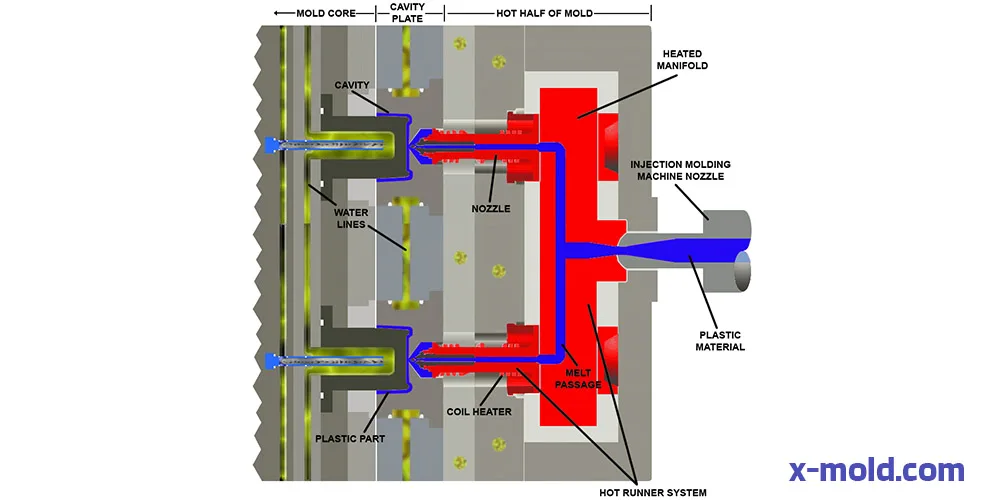
A hot runner mold is an advanced type of injection mold that uses a heated runner system designed to keep the plastic material in a molten state as it is injected into the mold cavities. Unlike cold runner systems, which allow the plastic to cool and solidify in the runners, hot runner systems use heated components to maintain the plastic’s temperature from the injection unit to the mold cavities. This process minimizes waste, enhances efficiency, and improves the quality of the final product.
Key Components
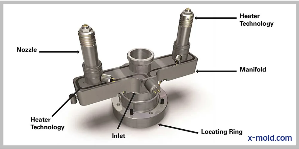
Manifold: The manifold ensures uniform temperature distribution. it is the central distribution component of a hot runner system. It channels the molten plastic from the injection unit to the various nozzles. The manifold is typically heated to ensure consistent plastic flow and temperature control.
Nozzles: Nozzles Inject the molten plastic into the mold cavities. They come in various designs, including open nozzles and valve-gated nozzles. Open nozzles are simpler and less expensive, while valve-gated nozzles offer better control and precision.
Heaters: Heaters are critical components that maintain the temperature of the manifold and nozzles. They include heating rods and rings to maintain high temperatures along the runner.
Temperature Controllers Box: They monitor and adjust the heat to maintain a consistent temperature, preventing material degradation and ensuring uniform part quality.
Hot Runner Mould Components
Different Types of Hot Runner Systems
Insulated Hot Runner Systems: Insulated systems use insulating materials to keep the plastic molten without direct heating. These systems rely on the thermal properties of the insulating material to maintain the plastic’s temperature. They are simpler and less costly but may not offer the precise control of heated systems.
Internally Heated Hot Runner Systems: In internally heated systems, the heating elements are embedded within the components, such as the manifold and nozzles. This design allows for precise temperature control and uniform heating, resulting in consistent plastic flow and high-quality parts.
Externally Heated Hot Runner Systems: Externally heated systems have heating elements positioned outside the plastic flow channels. These heaters indirectly heat the plastic, offering good control and temperature uniformity. Externally heated systems are often used for materials sensitive to thermal degradation.
How to Design a Hot Runner Mould?
Designing a hot runner mold involves several critical steps to ensure optimal performance, efficiency, and quality of the molded parts. Here is a step-by-step guide:
1: Initial Design Considerations and Requirements
Part Design and Specifications: Understand the geometry, dimensions, production volume, and features of the part to be produced. Consider factors like wall thickness, surface finish, and any special design features.
Number of Cavities: Determine the number of cavities based on production volume and cycle time requirements.
Gate Locations: Decide on the optimal gate locations to ensure uniform filling and minimize defects. Consider using simulation software to analyze flow patterns.
2. Selecting the Hot Runner System
Modular Design: Choose a hot runner system with a modular design for easy customization and maintenance. This allows for quick adjustments and efficient maintenance.
Consistent Melt Flow: Ensure the system provides a consistent melt flow to maintain part quality and reduce material waste.
Temperature Control: Select a system with an appropriate temperature control mechanism to avoid overheating or underheating the plastic, ensuring optimal flow and part quality.
Balanced Flow: Opt for a system with balanced flow to ensure even distribution of plastic into the mold cavities, reducing the risk of defects.
3. Designing the Manifold
Material Selection: Use materials like stainless steel or P20 for the manifold to resist corrosion and ensure durability.
Thermal Expansion: Design the manifold to account for thermal expansion, ensuring a sufficient sealing force to prevent plastic leakage.
Flow Channels: Design the flow channels to minimize pressure loss and ensure uniform temperature distribution.
4. Designing the Nozzles
Nozzle Type: Choose the appropriate nozzle type (e.g., open type, valve gate) based on the application and desired control over the plastic flow.
Placement: Strategically place nozzles to ensure uniform filling of the mold cavities and minimize flow paths. Ensure they are accessible for maintenance.
5. Gate Design
Gate Size and Location: Determine the size and location of the gate to ensure proper filling, reduce overpacking, and maintain dimensional stability of the part.
Gate Type: Select the appropriate gate type (e.g., hot tip, valve gate) based on the part design and quality requirements.
6. Thermal control
Heating Elements: Incorporate heating elements such as electric heaters or conduits to circulate hot oil, ensuring even heating of the system.
Cooling System: Design an efficient cooling system to stabilize the temperature and prevent heat transfer to the mold or machine platens.
7. Assembly and Testing
Component Integration: Assemble all components, ensuring proper fit and alignment.
Leak Testing: Conduct leak tests to ensure there are no material leaks in the manifold and nozzle connections.
Temperature Testing: Test the heating system to ensure uniform temperature distribution and proper functioning of the controllers.
8. Optimization and Validation
Flow Simulation: Use advanced flow simulation software to validate the design. Identify and address any potential issues with flow balance, pressure drop, or temperature variations.
Prototype Testing: Produce a prototype mould and run test cycles to evaluate performance. Make necessary adjustments based on test results.
9. Final Adjustments and Documentation
Design Adjustments: Make final adjustments to the design based on feedback from testing and validation.
Detailed Documentation: Create detailed documentation of the mould design, including component specifications, assembly instructions, and maintenance guidelines.
Troubleshooting Common Issues
Designing and operating a hot runner mould system comes with its own set of challenges. To ensure smooth operation and high-quality production, it’s important to identify and address common issues promptly. Here are some of the typical problems encountered in hot runner mould systems, along with troubleshooting tips and strategies for optimizing performance and extending mould life.
Common Issues and Solutions in Hot Runner Mold Design
Designing and operating a hot runner mould system comes with its own set of challenges. To ensure smooth operation and high-quality production, it’s important to identify and address common issues promptly. Here are some of the typical problems encountered in hot runner mould systems:
Material Leakage
Causes: Poor sealing between components, often exacerbated by damaged or worn-out O-rings or seals, can lead to leaks. Additionally, incorrect installation or assembly of hot runner components may also contribute to material leakage.
Solutions: Regular inspection and timely replacement of seals and O-rings are crucial steps. Ensuring proper torque settings during assembly helps prevent both overtightening and under-tightening, which can compromise sealing integrity. Finally, meticulous verification of component alignment during installation is vital to minimize the risk of material leakage.
Uneven Heating
Causes: Malfunctioning or improperly placed heaters may not distribute heat evenly across the workspace. Inadequate thermal insulation can lead to heat loss and variations in temperature. Additionally, defective thermocouples or temperature controllers may inaccurately monitor or regulate temperatures, contributing to uneven heating.
Solutions: Addressing uneven heating requires a systematic approach. Regular checks and calibration of heaters and temperature controllers are essential to maintain accurate temperature control. Ensuring proper placement and secure attachment of heaters and thermocouples can help optimize heat distribution. Additionally, employing high-quality thermal insulation materials helps minimize heat loss and promotes uniform temperature distribution throughout the system.
Flow Imbalance
Causes: Blockages or obstructions in the manifold or nozzles can disrupt the flow of material, leading to uneven distribution. Inconsistent heater performance, resulting in variable melt flow rates, can also contribute to flow imbalances. Additionally, improper flow channel design or machining errors may cause uneven flow patterns within the system.
Solutions: Regular cleaning and maintenance protocols should be implemented to remove any blockages and ensure unimpeded material flow. Monitoring and maintaining consistent heater performance is crucial to preventing fluctuations in melt flow rates. Utilizing flow simulation software during the design phase enables engineers to optimize flow channel designs, minimizing the risk of flow imbalances before implementation.
Gate Stringing or Drooling
Causes: During the injection molding process, excessive nozzle temperature can cause the material to flow uncontrollably through the gate, leading to stringing or drooling. Incorrect gate design or positioning may also result in improper material flow behavior. Additionally, inconsistent pressure control during the injection cycle can contribute to unpredictable material flow and gate issues.
Solutions: Optimize the nozzle temperature settings based on the specific material being used to prevent excessive flow. Review and adjust gate design and positioning to ensure proper material flow and gate closure. Moreover, maintaining consistent pressure control throughout the injection cycle helps regulate material flow and reduces the likelihood of gate stringing or drooling occurrences.
Cold Slugs and Flow Marks
Causes: Cold slugs and flow marks are often caused by deficiencies in the heating and injection processes. Inadequate heating of the manifold or nozzles can lead to localized cooling of the material, resulting in cold slugs and flow marks. Slow injection speeds can cause material to cool prematurely before filling the mold cavity, exacerbating the issue. Additionally, poor thermal conductivity in certain areas of the mold can create uneven cooling and surface defects.
Solutions: Increasing heater power or adjusting temperature settings helps ensure proper heating of the manifold and nozzles, reducing the likelihood of cold slugs and flow marks. Optimizing injection speed and pressure maintains material flow and minimizes premature cooling. Enhancing thermal conductivity through material selection and design modifications improves heat transfer within the mold, promoting more uniform cooling and reducing the occurrence of flow marks.
Burn Marks and Degradation
Causes: Burn marks and degradation issues often stem from factors related to heating, ventilation, and material behavior. Excessive heating or prolonged residence time of the material in the hot runner system can cause thermal degradation, leading to burn marks. Poor venting in the mold cavities can trap gases, exacerbating degradation and resulting in visible marks on the molded parts. Additionally, plastic degradation due to overheating can occur, further contributing to burn marks and degradation.
Solutions: Adjusting temperature settings to appropriate levels for the material being used helps prevent excessive heating and thermal degradation. Improving venting in the mold design by optimizing vent placement and size allows trapped gases to escape, reducing the likelihood of burn marks. Regularly purging the system with clean resin helps prevent material degradation by removing degraded material and contaminants from the hot runner system.
Conclusion
Designing a hot runner mould is key to making high-quality plastic parts efficiently. By understanding the components and addressing common problems, you can improve performance and extend mould life. Careful planning, precise design, and using advanced tools and expert advice are essential. With these strategies, and you’ll achieve top-quality moulded parts and a more efficient manufacturing process.
FAQ
What material is used for hot runner mould?
The materials used for hot runner components are selected based on their ability to withstand high temperatures, pressures, and the specific properties of the plastic being molded. Such as tool steels( H13, S7, 420 Stainless Steel), copper alloys, nickel alloys, beryllium copper, etc.
What is the difference between sprue and runner?
Sprue: The sprue is the primary channel through which molten plastic flows from the injection moulding machine into the mould cavity. It is the initial entry point for the plastic material and is typically located at the parting line of the mould.
Runner: Runners are the channels that distribute the molten plastic from the sprue to the individual cavities within the mould. They guide the flow of plastic and ensure even distribution to each cavity.
What is the difference between a hot runner mould and a cold runner mould?
Hot Runner Mould: In a hot runner mould, the runner system is heated, allowing the plastic material to remain molten as it flows from the injection unit to the mould cavities. This eliminates the need for solidified runners, reducing waste and improving efficiency.
Cold Runner Mould: In a cold runner mould, the runner system is not heated, causing the plastic material to solidify within the runners after injection. These solidified runners must be removed and recycled, resulting in increased material waste and longer cycle times compared to hot runner moulds.